Machine vision systems
We are one of the few machine vision systems providers who possess the technical expertise needed to develop bespoke computer vision software.
This enables us to deliver customized systems that allow higher image processing speed and shorter response time than the solutions built using generic computer vision libraries.
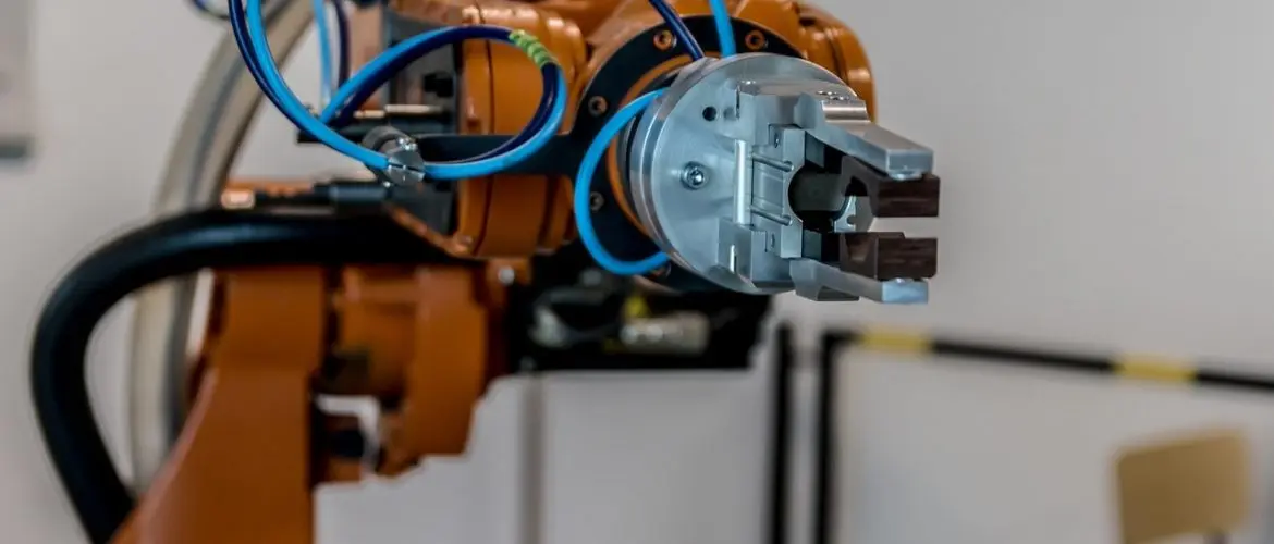
Optical System for Part Recognition
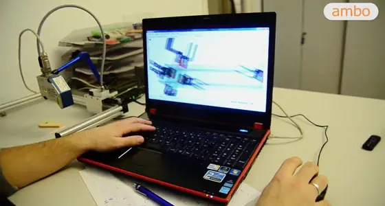
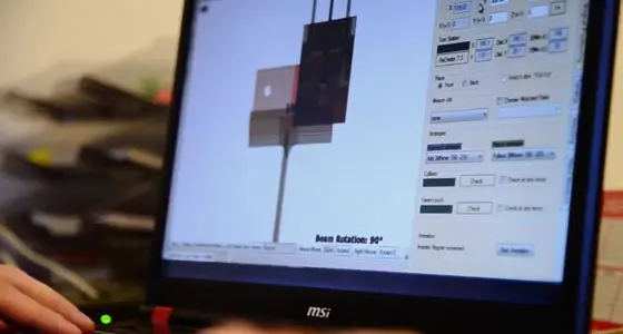
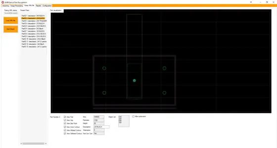
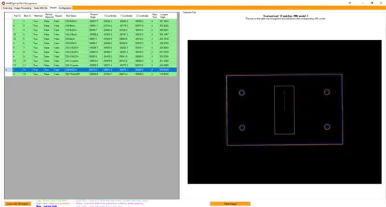
The Optical System for Part Recognition is an accurate and powerful object detection system that helps to cut costs and boost overall process efficiency across manufacturing environments.
The industrial technology system consists of a smart 3D camera and our proprietary image processing software that can automatically measure, inspect, identify and recognize objects on an assembly line.
The device uses digital laser sensors protected inside industrial cameras with specialized optics to capture 3D point clouds by performing sweeps across the assembly line. The viewpoint and the scanner trajectory can be modified to meet exact needs. The images of products are processed at the speed of the assembly line.
For standard parts, with fewer size differences, on a 10 meters long conveyor transporting an average number of 30 parts, the application needs about 2 minutes (including the 45-60 seconds required for scanning) to recognize the pieces.
Once the matching process for all parts within a project section is completed, the robot pick-and-places the parts on a beam where it will be first tacked and afterward welded. The image library is heavily optimized, thus ensuring higher processing speed. Moreover, the application was designed to allow more project sections (beams) to welded within a single scanning operation.
We provide the machine vision system either entirely or partly, from image processing algorithms to the ready-to-work system of a camera, processor, software and DLL integration. It is easy to combine the application with robotized or manual equipment.
Software
We have our own developed proprietary software for our machine vision systems. This allows our systems to produce an increased quality of image processing and thus to work faster and more reliably.
Industrial Cameras and Vision Sensors
Most of the industrial camera systems produced nowadays have on-board image capture and processing capabilities. Therefore, in the case of straightforward applications, there is no need to send the image data back to a remote PC for processing. The results of the automated optical inspection are sent to a PLC over industry standard connections such as Ethernet. Complex applications still require a connection of a camera and PC.
The most complex projects, where for eg. there is a need to differentiate individual product parts by shape or color, the usage of 3D smart cameras is typical.
Smart vision sensors are imagers, usually including embedded light sources, which can determine the orientation, shape and position of items. They are also used to inspect for assembly faults, defects and missing features.
Partner Technology
![]()
Minimum Hardware & Software Requirements
• Work memory: 8 GB or higher;
• Dedicated Ethernet Gigabit Network Card;
• Windows 7 (32, 64 bit);
• Camera specific libraries.
Automated detection systems can perform a wide array of industrial automation tasks on the assembly line. This allows manufacturers to minimize production costs while increasing productivity and overall efficiency. Nowadays machine vision systems and tools have multiple industrial applications, from bar code verification to flaw detection and automatic inspection.
The Optical System for Part Recognition can be employed for a wide spectrum of industrial applications. With over a dozen active machine vision systems installations, all utilizing our proprietary machine vision software, we have the experience and knowledge to implement a system in the shortest time. Depending on the intended area of use, each machine vision system application involves a unique end of arm tooling.
Automated Welding
The Optical System for Part Recognition is deployed in many welding applications, eliminating the need for complex and costly welding fixtures. Other benefits result from acting as an alternative to skilled human welders.
The Optical System for Part Recognition integrated system is positioned above a conveyor transporting metal parts. The system uses digital sensors protected inside industrial cameras with specialized optics to measure, inspect, identify and recognize images of products at machine speed. The industrial system provides instant results at the speed of the assembly line. The raw information captured by the sensors is sent to the main computer, to be processed by the Optical System for Part Recognition specialized software. The software compares the received data with a set of predefined CAD models of known objects, thus producing a set of data for the pick-and-place robot, detailing the position and orientation of each of the items.
Much of the success of any machine vision application is determined by lighting. Cameras are not able to “see” the objects, but the light reflected from objects towards them. Light reflection or possible differences of the objects have an impact on the overall accuracy of the result. To compensate for such inconsistencies, the system allows for a predefined matching tolerance. Also, a human operator is given the possibility to manually match parts on the assembly line. The application also performs quality assurance inspections of the scanned parts, as their dimensions can be analyzed.
During the matching process, the results can be visually analyzed. The matching parts are identified by their related images, providing a visual check of the real part versus the ideal model. To avoid multiple picks of the same item or robot-to-part collisions, the system performs a collision check before allowing the robot to perform any pick and place operation.
Other Applications
• measurement (measuring and testing a product’s specific dimensions);
• visual inspection (verifying the correct position of the objects on an assembly line);
• product identification (bar code reading, identifying products based on size, shape, etc.);
• sorting products (for example, sorting packaged chocolate bars by color, etc.).
Piece-orientation
The parts on the conveyor can be placed in any position, as the system is able to identify them no matter of their angle. The key condition is that the objects should not overlap, so they can all be scanned individually.
Fast setup time
Installing the application takes only a few moments. However, as with all complex systems, the calibration of the scanner and the conveyor reference is more time-consuming.
Rate of recognition
The scanning accuracy has a tolerance of less than 0.5 mm. Given this metric, in an ideal working environment where thee are no differences between the scanned parts, there would be a full recognition rate. Within a real working environment, there are always differences between the ideal and real part dimensions, as the cutting process is not always completely accurate. For such a situation the application allows a tolerance limit on the part dimensions to be automatically matched.
Can deal with different parts at a time
The system is able to detect all parts on the conveyor, as it checks for a predefined set of parts, needed by the current project section. The predefined parts can have different shapes and heights, with holes drilled inside them. Apart from plate-like parts, the application can recognize I, C, O, and L profile parts, all of them having different contours and a different number of holes.
Reduced scanning times
On a 10m length conveyor, the scanning process takes about 45-55 seconds. The entire process, including both scanning and processing the data, takes about 2 minutes, depending on the environment and the length of the conveyor.
Flexibility: adapts to any production line
The system can be used on various machine types. The only requirement is to have all the objects presented to the scanner. To increase the productivity one can employ several instances of the system on the same production line.
User-friendly
The GUI of the application is as clear and straightforward as possible. The human operator’s tasks are reduced to press the start button and visually checking the automated matching results (and in some cases to manually match some unmatched parts).
Training
The unit can be used with minimal operator training. Usually, the first training session takes place once the system is delivered. Other training sessions are held if there are new members in the team, or the system has been upgraded.
The system can handle varied lighting conditions
The recognition rate is affected by size differences of the parts placed on the conveyor (dimensions can slightly differ from one part to another), the finish of the parts (deep scratches can alter the data acquired by the scanner), the ethernet connection of the optical device and the fluctuations in illumination intensity.
Quality Control System
• Scalable
• Fully customizable
• Easy to use GUI interface
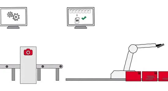
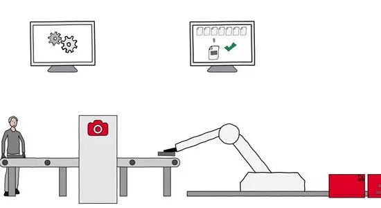
The automated Quality Control System detects defective products in the production line, thus enabling manufacturers to increase production speed and efficiency on the factory floor.
The Quality Control System is equipped with a 3D camera to acquire data and to analyze the 3D objects to be sorted based on the given criteria.
It works in a similar way to the Optical System for Part Recognition machine vision system, but with different automation. The recognition process can be performed in less than 10 seconds, including the scanning stage which is about 6 seconds. The Quality Control System’s challenge is to search the matching model into large databases, that can include 20000+ items to be checked.
Compared to the traditional quality control works performed by human operators, computer vision-based automated quality control systems include the benefit of working work in hazardous environments 24/7. Also, it can perform quicker measurements with higher accuracy and consistency than the human operators.
Software
All our machine vision automation systems use proprietary software. This allows an increased quality of image processing and makes our systems work faster and more reliably.
Industrial Cameras and Vision Sensors
Most of the camera systems produced nowadays have on-board image capture and processing capabilities, therefore, in case of not complicated applications, there is no need to send the image data back to a remote PC for processing. The results of the inspection are sent to a PLC over industry standard connections such as Ethernet. Complex applications still require a connection of a camera and PC.
For the most complex applications, where for eg. there is a need to differentiate individual product parts by shape or color, the usage of 3D smart cameras is typical.
Smart vision sensors are imagers, that can identify the orientation, shape, and position of objects. They can also inspect for assembly faults, damaged parts, and missing features.
Partner Technology

Minimum Hardware & Software Requirements
• Work memory: 8 GB or higher;
• Dedicated Ethernet Gigabit Network Card;
• Windows 7 (32, 64 bit);
• Camera specific libraries.
Quality control systems based on computer vision are able to inspect products moving on an incoming production line and detect faulty items, that can be then removed before the final steps of production.
The Quality Control System can prevent product rejection by detecting all defective products, while also avoiding false defect detections. This industrial automation system is currently used to verify and sort metal pieces by dimensions.
Piece-orientation
The parts on the conveyor can be placed in any position, the system is able to identify them no matter of their angle. The key condition is that the objects should not overlap, so they can all be scanned individually.
Fast setup time of recognition
The scanning accuracy has a tolerance starting with 0.5 mm. Given this metric, in an ideal working environment with no differences between the scanned parts, it would result in a full recognition rate. Within a real working environment, there are always differences between the ideal and real part dimensions, as the cutting process is not always completely accurate. For such a situation the application allows a tolerance limit on the part dimensions to be automatically matched. The part on the conveyor is compared with a huge predefined set of parts. The predefined parts can have different shapes and heights, with holes drilled inside them. Apart from plate-like parts, the application can recognize I, C, O, and L profile parts, all of them having different contours and a different number of holes.
Reduced scanning times
On a 2 meters length conveyor, the scanning process takes about 5-6 seconds. The entire process, including both scanning and processing the data, takes about 11-13 minutes, depending on the part dimension and the dimension of the database with the predefined models.
Flexibility: it adapts to any production line
The system can be used on various machine types. The only requirement is to have all the objects presented to the scanner.
User-friendly
The GUI of the application is simple, and it presents the result of the scanning process for each step.
Training
The unit can be used with minimal operator training. Usually, the first training session takes place once the system is delivered. Other training sessions are held if there are new members in the team, or the system has been upgraded.
The system can handle varied lighting conditions
The recognition rate is affected by the following factors:
– the size differences of the parts placed on the conveyor (dimensions can slightly differ from one part to another)
– the finish of the parts (deep scratches can alter the data acquired by the scanner)
– the Ethernet connection of the optical device and
– the fluctuations in light intensity.
Object Localization System


• Can handle various shapes and sizes
• Fully customizable
• Easy to use GUI interface
• Rapid setup
The Object Localization System is an industrial object detection and localization system that can discover the location of 3D objects in order to guide your robot to the desired point for pick and place operations.
The system consists of a 3D camera that acquires 3D point clouds by performing sweeps with a laser sensor and a smart software system that can identify the location of the objects based on the acquired 3D point clouds. It is a complete system that easily connects to your robotic arm.
The intelligent camera is installed above the pile of objects to be picked and placed. The Object Localization System suits most storage types: from bins, boxes, conveyor belts, pallets, to tables or trays, containing overlapping, arbitrarily-shaped items.
The industrial system is able to accurately determine which object, located on the top of the pile, is the easiest to grasp among the pick-up candidates. Subsequently, the automated system sends the robot the 3d pose of the part so that the robot can further successfully manipulate the workpiece among randomly stacked parts. The robotic arm picks and places the part on the desired location – for example on a conveyor where the part is scanned and inspected, depending on the existing requirements. Next, the pick-and-place process is performed as a repetitive path pattern.
Human pick-and-place operations demand repetitive motions taking place over an extended amount of time. The Object Localization System can streamline the operations in your company by automating the monotonous, repetitive pick-and-place tasks. This allows the workers to focus on higher value operations.
The Object Localization System can come with different setups to handle products of any size, from small to large.
Software
We can develop bespoke machine vision algorithms for visual recognition of randomly mixed products.
Camera
The camera provides the robotic arm with the 3D vision. The camera’s specifications (such as lens characteristics, sensor size, focal length, etc) are application specific. Our team will help you identify the camera that best meets your requirements.
We have experience with many system types from all major industrial camera brands, such as:
![]()
![]()
![]()
Robots
The Object Localization System is compatible and easy to integrate with most leading industrial robot systems, such as:
![]()
![]()
![]()
Calibration
Camera calibration, allowing to transform the pixel measurements into real-world coordinates, is critical for achieving the highest accuracy in the machine vision system. The calibration process is performed in a quick and uncomplicated manner via TeamViewer remote access.
Training services
Operating the Object Localization System is pretty straightforward. The system doesn’t require any special training and it can be operated by non-vision experts, but if any help needed we gladly assist.
Maintenance and support
Our support services include online access to our machine vision engineers, Service Level Agreements tailored to meet your specific needs, and call out services.
Minimum Hardware & Software Requirements
• Work memory: 8 GB or higher;
• Dedicated Ethernet Gigabit Network Card;
• Windows 7 (32, 64 bit);
• Camera specific libraries.
Object detection and localization is a very productive field, with a lot of traction in manufacturing and commercial applications. The Object Localization System machine vision system is currently used in a pick-and-place application for automated welding. We can easily adapt it to meet various use cases.
Assembly
Pick and place machine vision systems are able to recognize, grasp and transfer parts from one work area (conveyor belts, pallets, bins) onto another for assembly. Example: the robotic system can bring chair parts onto a conveyor for assembly.
Packaging
Alike the assembly processes, the pick and place robots can grab parts from one work area and instead of assembling the part, the system places it in a packaging container at a high speed. Example: the robotic system can pick up fruits from containers in a warehouse, transport and automatically place them in a packaging container at a high speed.
Bin Picking
Pick and place robotic systems outfitted with sophisticated vision systems can grab parts out of a bin and place them on the production line, even if parts are randomly mixed together.
Counting
One simple use of object detection, corresponding to a broadly required need, is counting. Computer vision based systems are able to count either people, cars, furniture parts, or even microorganisms.
Other Applicabilities
• Loading and unloading objects from conveyors, trays or boxes
• Racking and de-racking
• Palletizing and de-palletizing
Each of these applications involves different approaches with respect to the processing time (real-time, off-line, on-line), resistance to occlusions, illumination variations, geometric deformations, and detection under pose changes.
Unlike other application detecting a single object class from a single viewpoint, the Object Localization System can detect multiple object classes from multiple views
• Can recognize products of varying sizes and shapes, from simple geometric pieces to complex shapes;
• Fully customizable to meet specific production requirements;
• Fast setup time;
• Easy to use interface;
• Can integrate with any camera;
• Can detect all materials: e.g. metal, polymer, and wood;
• Flexibility: adapts to any production line.
Tech stack
What is your challenge right now?
Backed by more than 20 years of experience and 300+ completed projects, we’re confident that we can help you no matter the challenge.
